Introduction
This is an installation piece centred around the theme of systemic collapse as a loose allegory for climate change. The idea would be for viewers to partake of free wine on offer in the bird bath, as one customarily would at student exhibition private views. The interaction of the descending level of the liquid would then begin to trigger birds hidden around the space to begin pecking at the floor or walls they are stood on. The end result of this is intended to be a steady climb over time until there is a cacophony of these birds, the motors and the tapping sound of their beaks, such as to make them unignorable.
Concept and Background Research
My artistic practice is interested in the ideas of systemic collapse, and ways in which systems can be built to engage an audience in the system’s destruction or dysfunction but without holding any one audience member accountable. I see this as a way to investigate issues of climate change, financial insecurity and social inequalities as it is unhelpful to scapegoat individuals when the root causes of these problems are systemic.Inspiration for this method of work comes from the AutoDestructive Art movement and particularly the work of Jean Tinguely and works such as Homage to New York, 1960.(Tinguely 1960) Following from this tradition come the work of Michael Landy with Break Down (Landy 2001) and Cornelia Parker’s Cold Dark Matter (Parker 1991) where destruction is the mechanism by which artistic metaphor is created.
Technical Implementation
The Pecking Bird
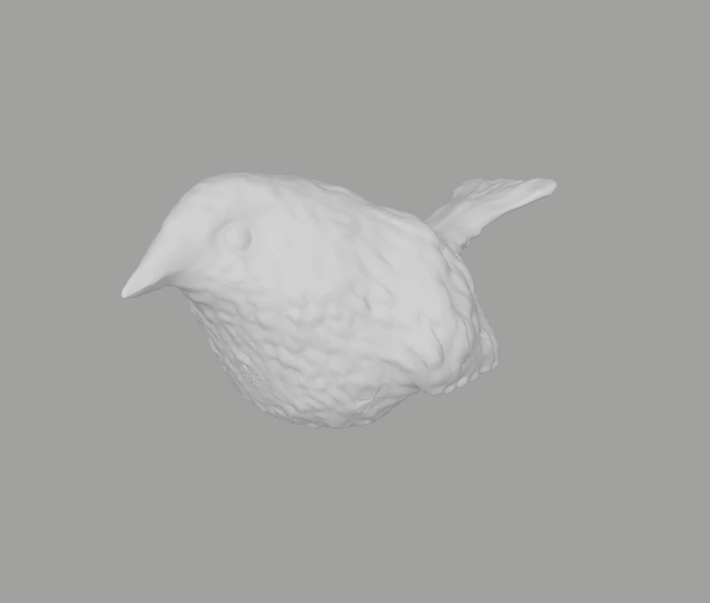
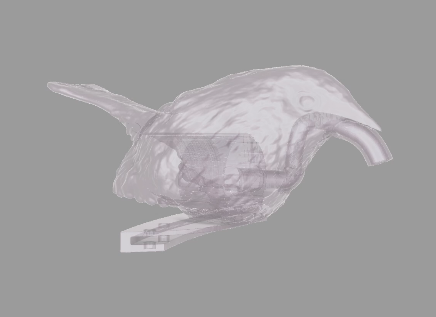
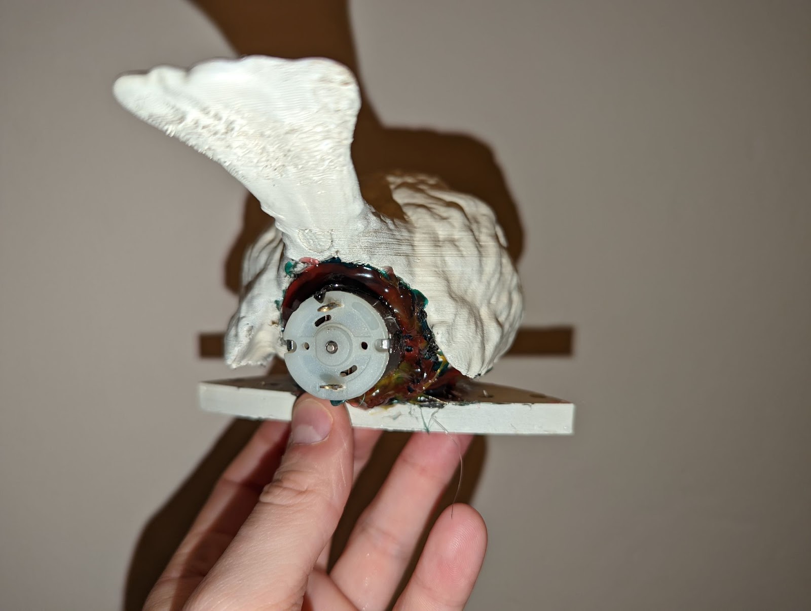
The bird itself was modelled in ZBrush before being moved into Autodesk Maya where I could add the CAD elements that had been drawn in Fusion 360.The first aspect I tackled was the mechanism by which the pecking occured. I attempted using rack and pinion systems but was unable to get the movement I wanted before trying with a geared system. A DC motor would turn and as the teeth interlocked, the bird would be cocked back, tensioning a spring which would cause it to violently swing back when the driving gear was toothless.
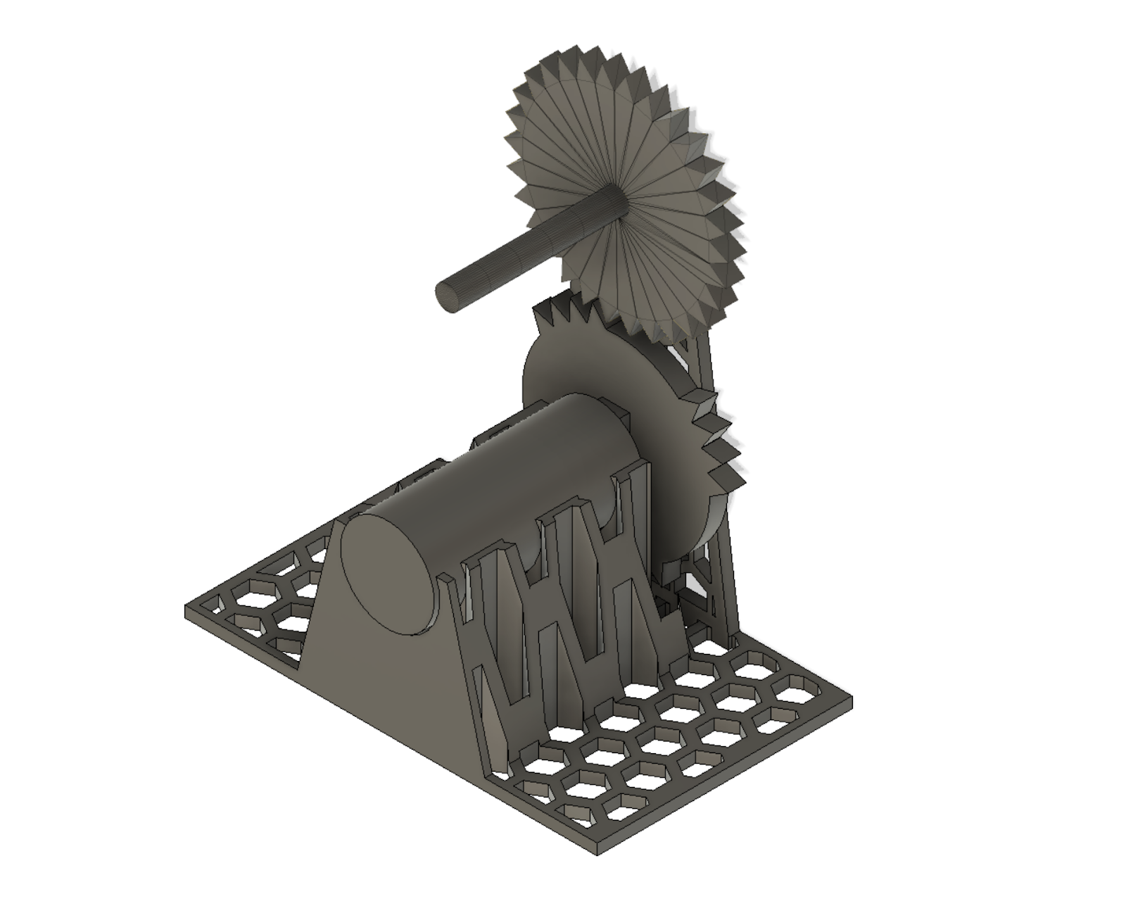
This was too violent and ultimately unreliable as the motor would soon chew through the PLA and no longer stretch the spring.
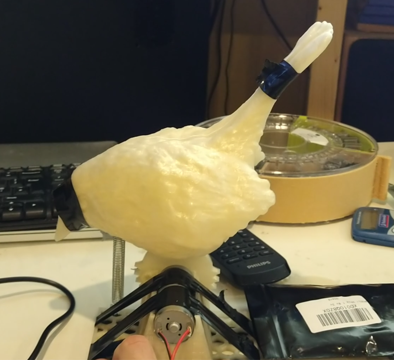
Moving to a servo-arm driven mechanism worked much better and more reliably, but the issue I had was packaging. The entire system was too artificial – how could it look like it was a bird pecking at the ground when it was suspended 10cm up in order for the arm to work?
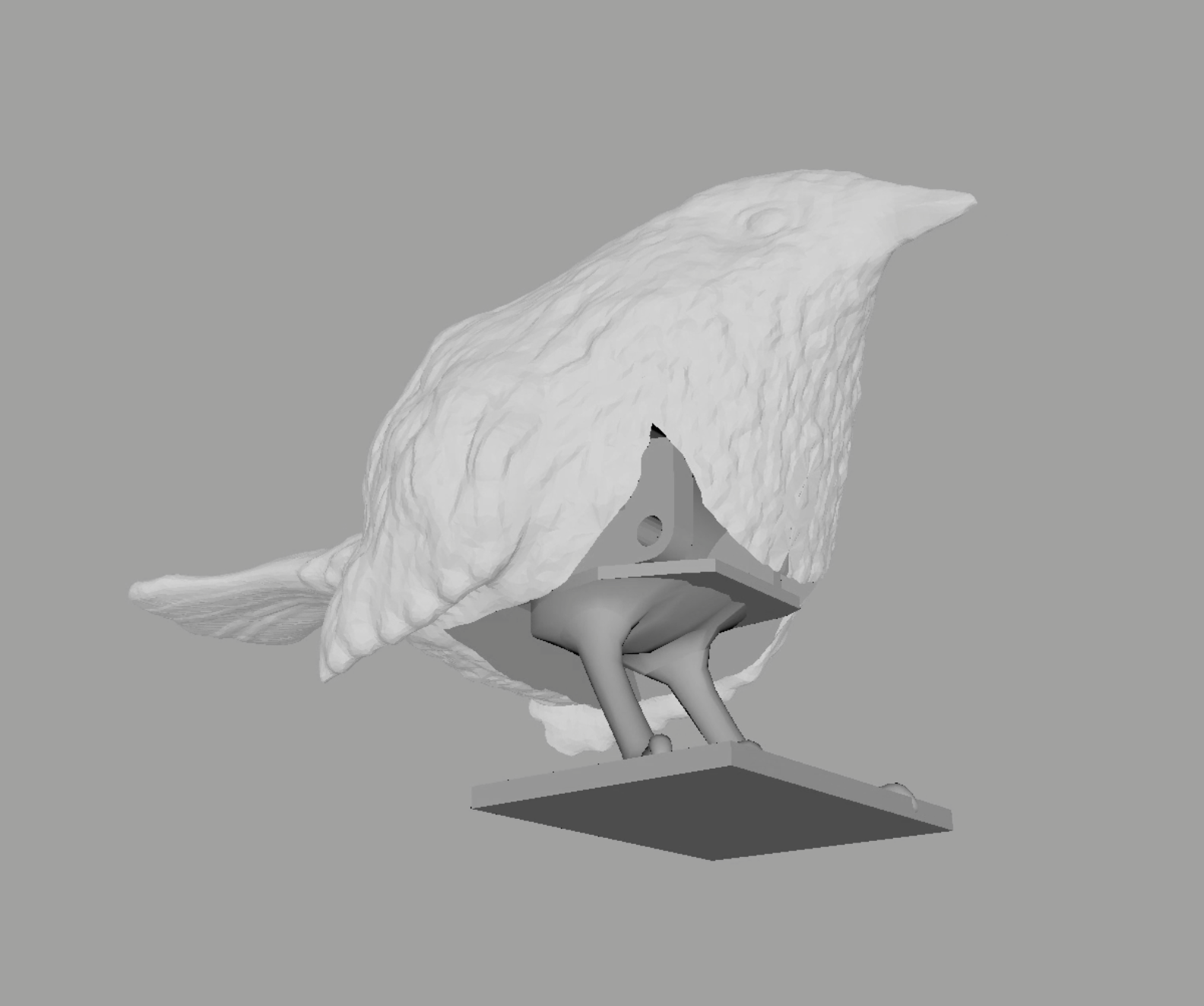
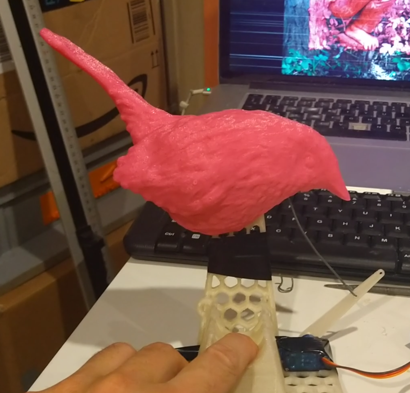
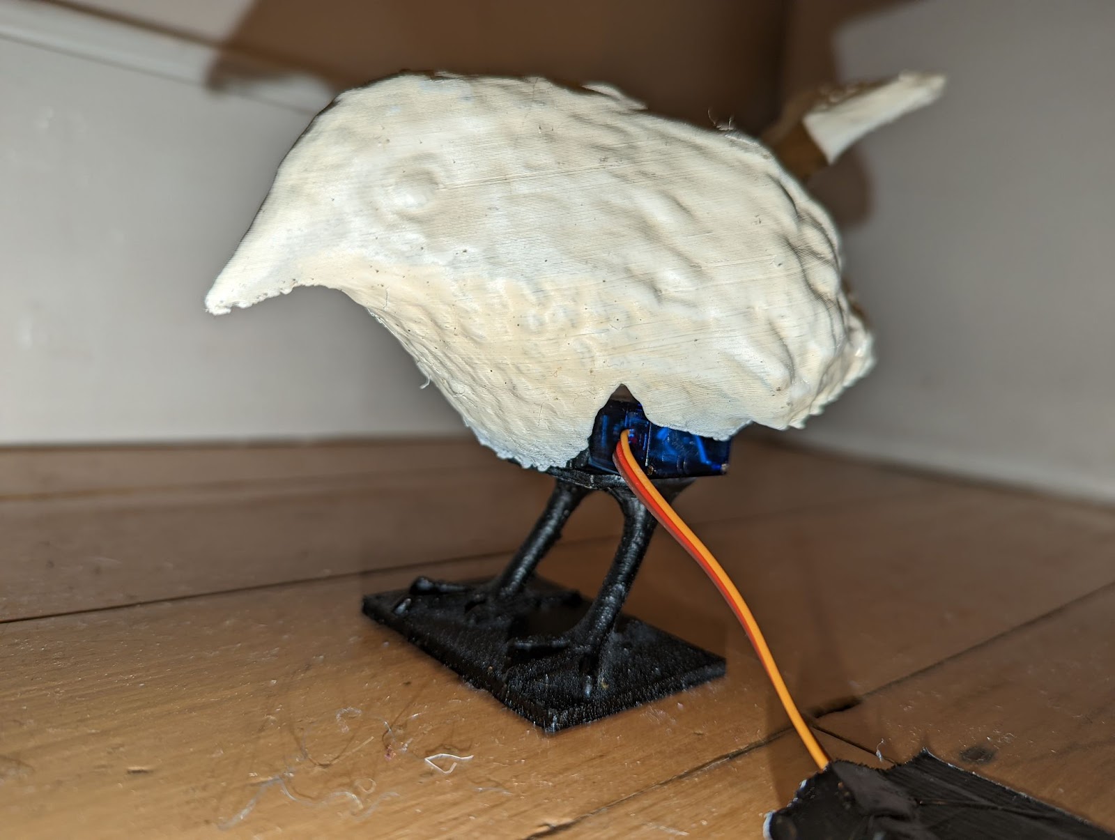
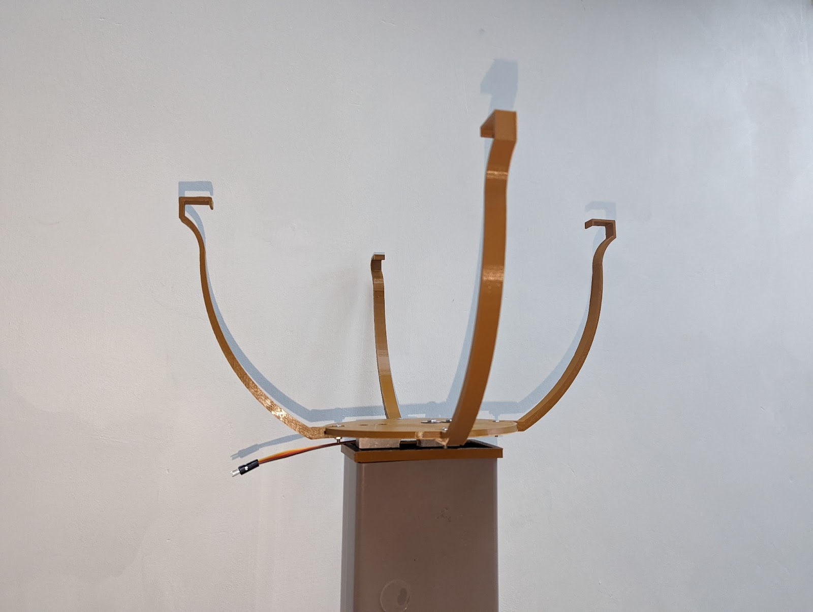
My solution was to put the arm inside the bird itself, and the servo on a platform hidden within the body but stood on bird legs which in turn were stood on a platform which I could glue or screw onto a surface. I tried having a removable arm and a gap for the bird to sit on it, but felt this was likely to work its way loose, so eventually ended up with an “L” shaped armature protruding from the inside of the bird, maintaining the body’s position relative to the servo and thus the legs, providing clearance.
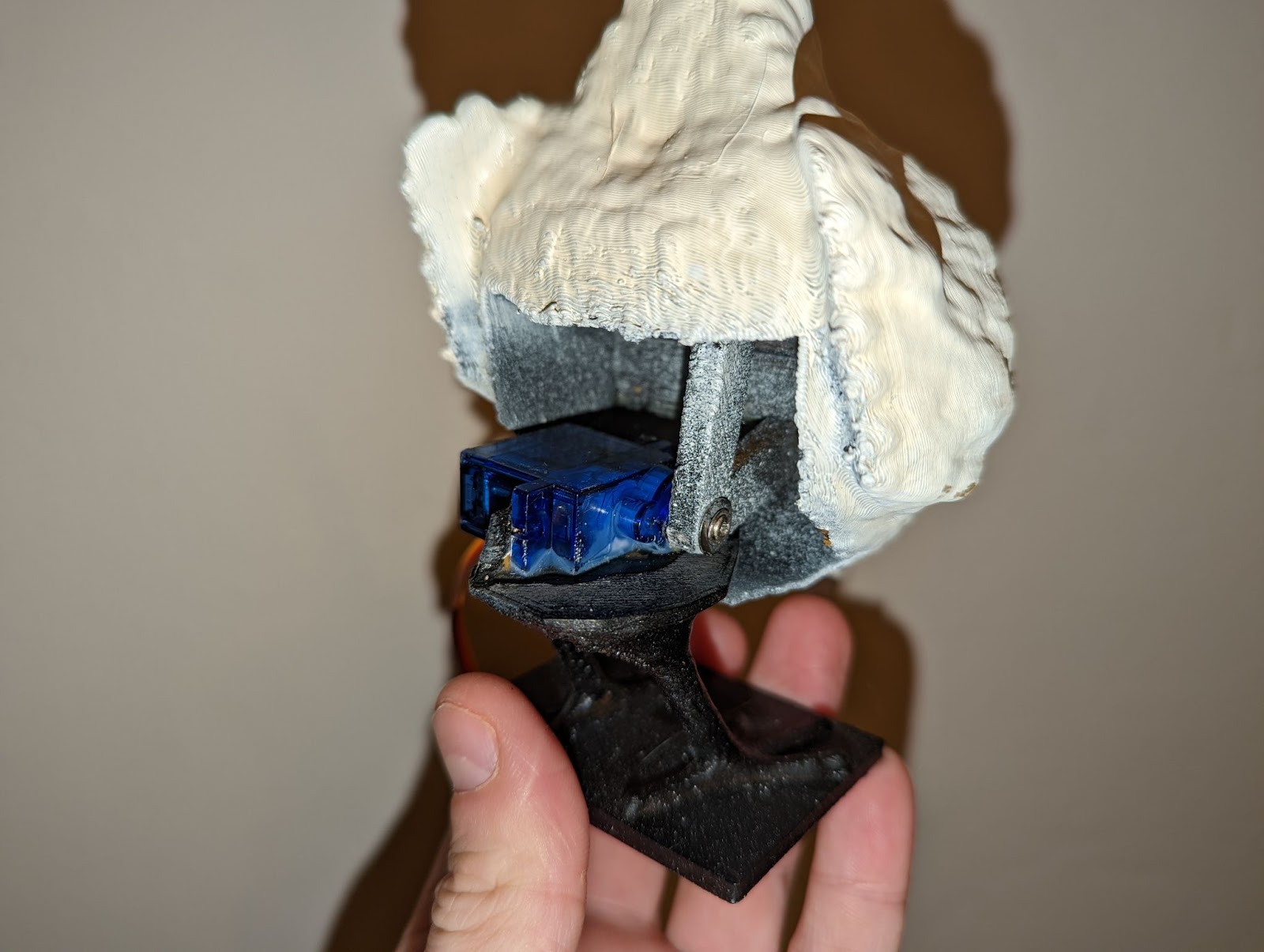
I did have a large, recurring issue with this however, and that was the method for attachment to the servo motor and alignment with 0. Running a program to turn the motor to 0 and then screwing or glueing the bird to the motor wouldn’t work every time. The hole for the arm had to be slightly enlarged to accommodate the motor shaft (probably due to slightly inaccurate measurements or printing calibration), and occasionally this enlargement would be too much and the shaft would turn without moving the bird. Otherwise the 0 would be misaligned by the shaft turning when screwing the arm in. Or perhaps too much was asked of the servos, or they were being asked to turn when the birds physically couldn’t and it caused them to burn out. Whatever the cause, I was unable to find a reliable attachment method and this led to a number of servos stopping working. This was also perhaps a major cause for why I was never able to fully implement the whole installation, servos failing or shorting out, causing the arduino to crash.
The Pump
One of the aspects of this project I am most proud of and yet, like all other parts, is incomplete and unsatisfactory, is the pump mechanism. When first conceiving of this project, my initial thought was that people would ladle themselves wine. I began to imagine problems however, as my first idea for a sensor mechanism was a light dependent resistor and with a ladle moving in and out of the liquid this would create a degree of sloshing that may trigger the sensor too early. When I changed the sensor to a load cell I thought that the weight of the ladle and people using it may also cause some issues. This then led me to the conclusion to include a pumping mechanism, which may itself be triggered by a sensor. As it is I have implemented the pump to be triggered by a button instead.
Upon thinking of using a pump, I knew it had to match the sculptural theme I was creating, i.e. that of a bird and so I adapted my model to be able to accommodate a DC motor pump that I had taken from a drinks pump bought for the purpose. The first version I printed turned out to be the wrong way round, and it was extensive faffing about with models in Maya and Meshmixer to be able to sort one that did work.Hot glue was used to hold the motor firmly in place and attempt to create a watertight seal. This wasn’t fully effective.
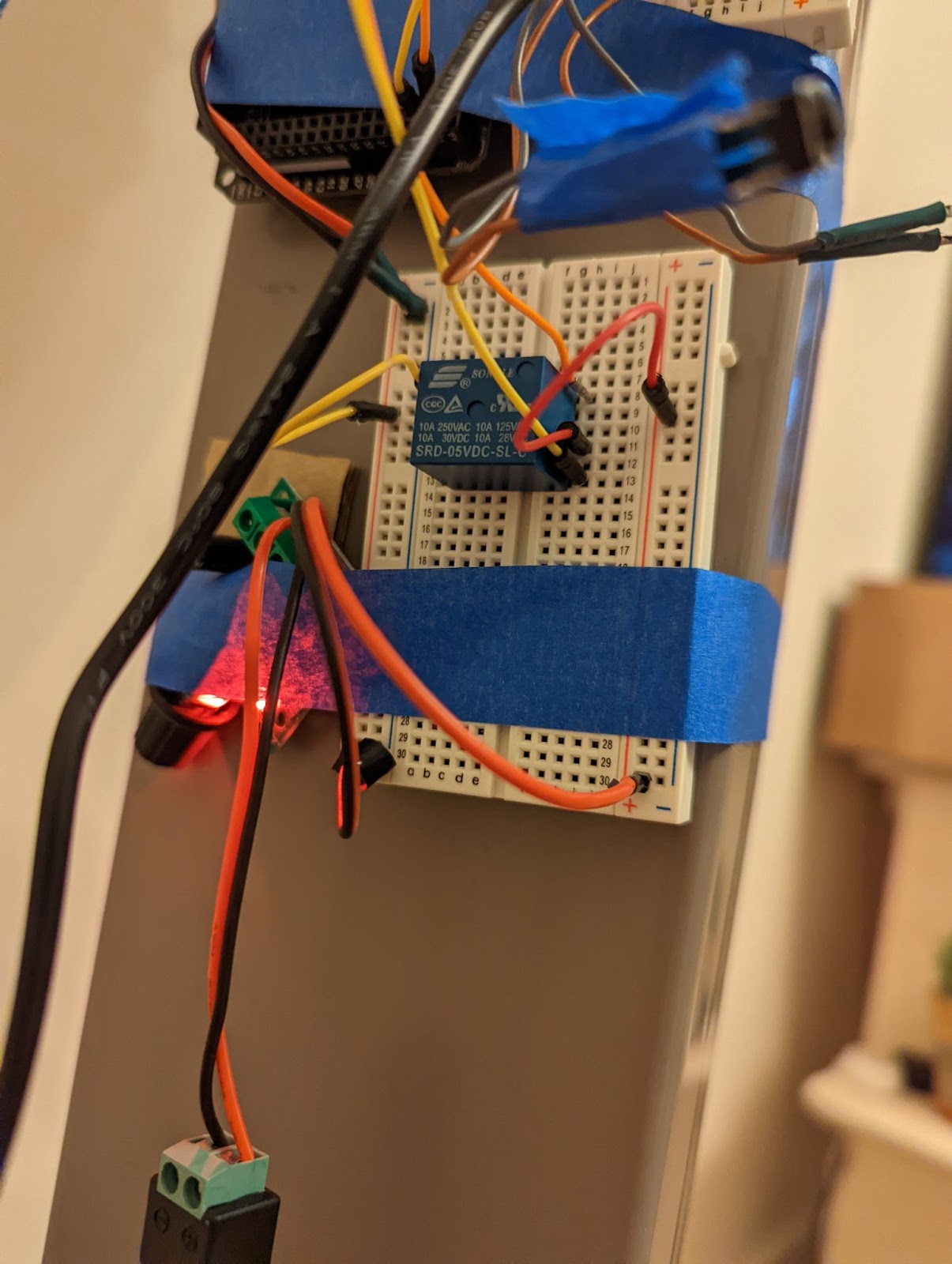
The motor wouldn’t run with the 9V power supply, so I had to implement a relay circuit to trigger a 12v power supply to be able to run it. In line with the circuit is also a potentiometer that helped regulate the speed of the motor.
The Load Cell
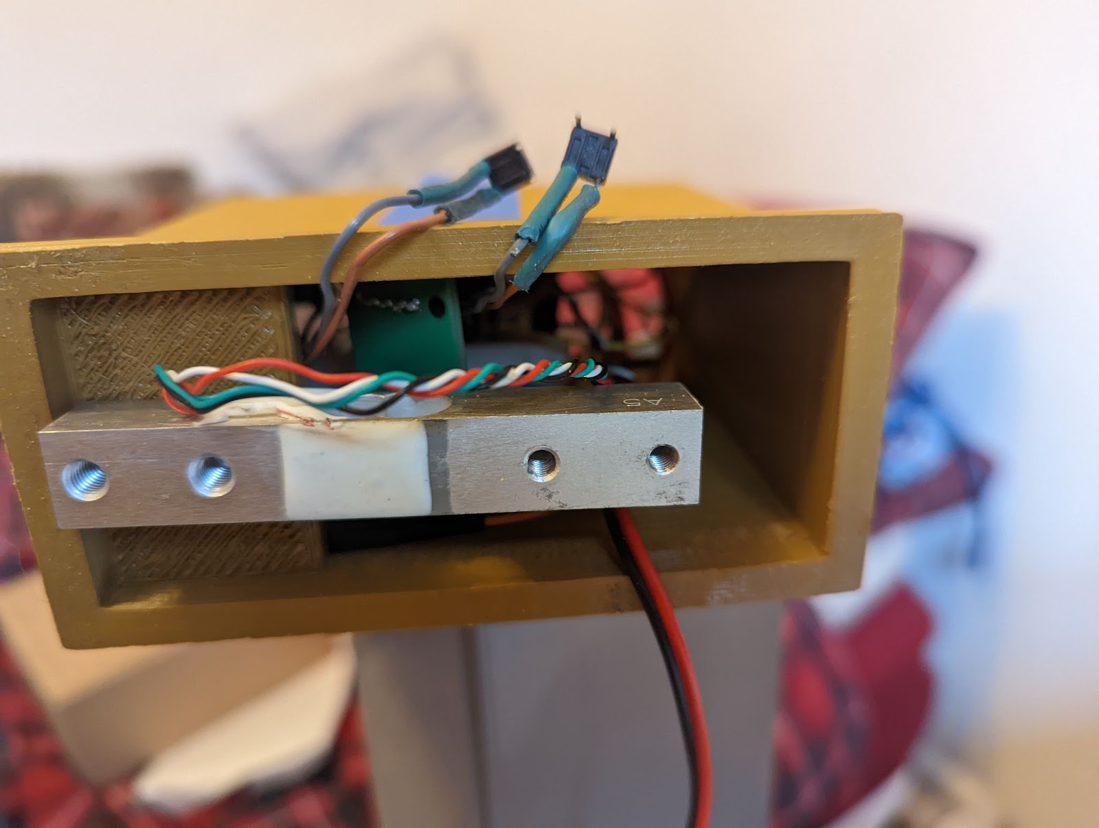
The load cell was set on a housing that would slot into the top of the post section. This housing turned out to be too short so the bottom was cut off and then due to unreliability of the system as a whole I stuck the circuits to the outside while I was still working on it. Attached atop of the loadcell is the holding point for the basin, which would push down onto the load cell and measure the weight.
This worked, but the cell seemed to lose a gram every few seconds or so. I am unsure what the cause of this is, perhaps the plastic housing bending to accommodate the weight and thus reducing the strain on the load cell? A coding issue? An electrical issue? The load cell attachment being too spread out? This last point seemed to be the issue behind a loss of accurate measurements that occurred occasionally, but has yet to be tested.
Power issues
Finally, the aspect of the project that has caused the most anguish were issues with power. I have a number of 12v dc transformers. I believed that one of these would be appropriate to power the arduino. I thought this because the external power board has a marking on it saying Vin<12V (or perhaps it says V1n<12V in which case I have no idea what it means) and the commonality of 12v dc transformers. However, the use of these fried the serial connection for two arduinos leading to avrdude errors. And for one of the arduinos this meant the port was completely invisible.This problem wasted a considerable amount of time and the cost of two arduino units. I struggled to find any straight information online contradicting the use of a 12v power supply or the amount of amperage involved that may contribute to such an issue.
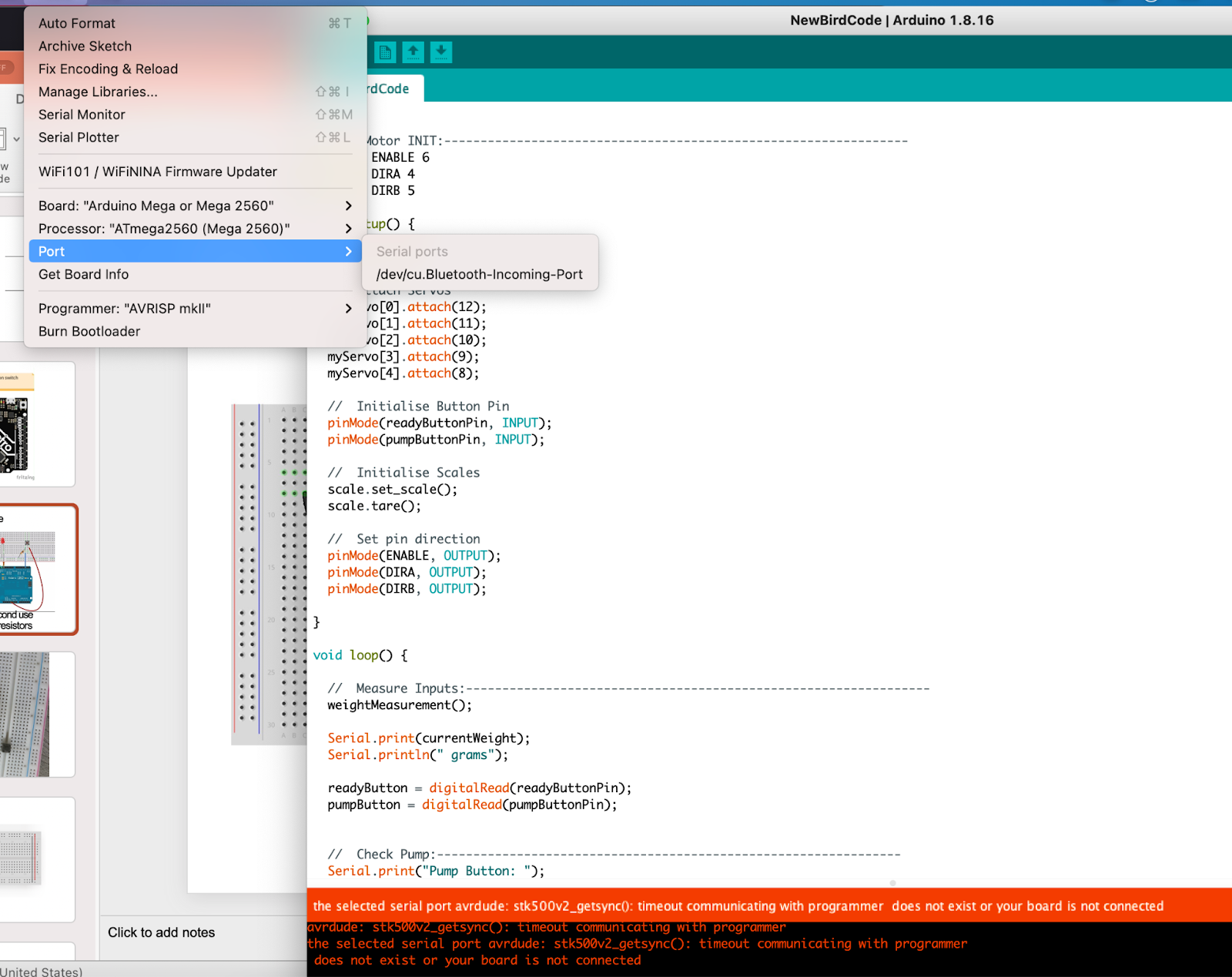
Eventually, a solution was found in a 9v power supply as matched those that others in class had. But due to the nature of my issues and the uncertainty in their origin, I had to test all aspects of my project very slowly without the external power to make sure the entire system worked in a basic sense before attempting to actually run it all together, just in case it bricked another arduino which would have been too late to purchase another in time.
Reflection and Future Development
I am left very hollow at this juncture towards this project as it is as yet unfinished, ugly and unsatisfactory. I am happy to have identified and overcome a number of hurdles e.g the power issues, and the use of a relay, but as of writing the object isn’t fully painted and a new housing needs to be made to support the electronics as well as housings made for the two buttons. Although the project was ambitious, I do think it was achievable in the time frame. I will finish this piece ready to install somewhere and working reliably, as it is something I have had in my head for a long time. The main issues that I need to address are the servo issues, which may be solved using metal gear servos (though I abhor simply throwing money at problems for solutions) with threaded inserts for a proper attachment, the load cell losing weight over time and the pump effectiveness.
Parts List
1 x Elegoo Mega 2560 R3
1 x Elegoo Power MB V2
1 x Elegoo L293D chip
1 x Songle SRD-05VDC-SL-C relay
2 x Button
2 x 10k Ohm Resistor
1 x HX711 load cell
1 x DC motor pump (Part number unknown)
1 x 9v 1A Power Supply
1 x 12v 3A Power Supply
1 x Potentiometer (Part number unknown)
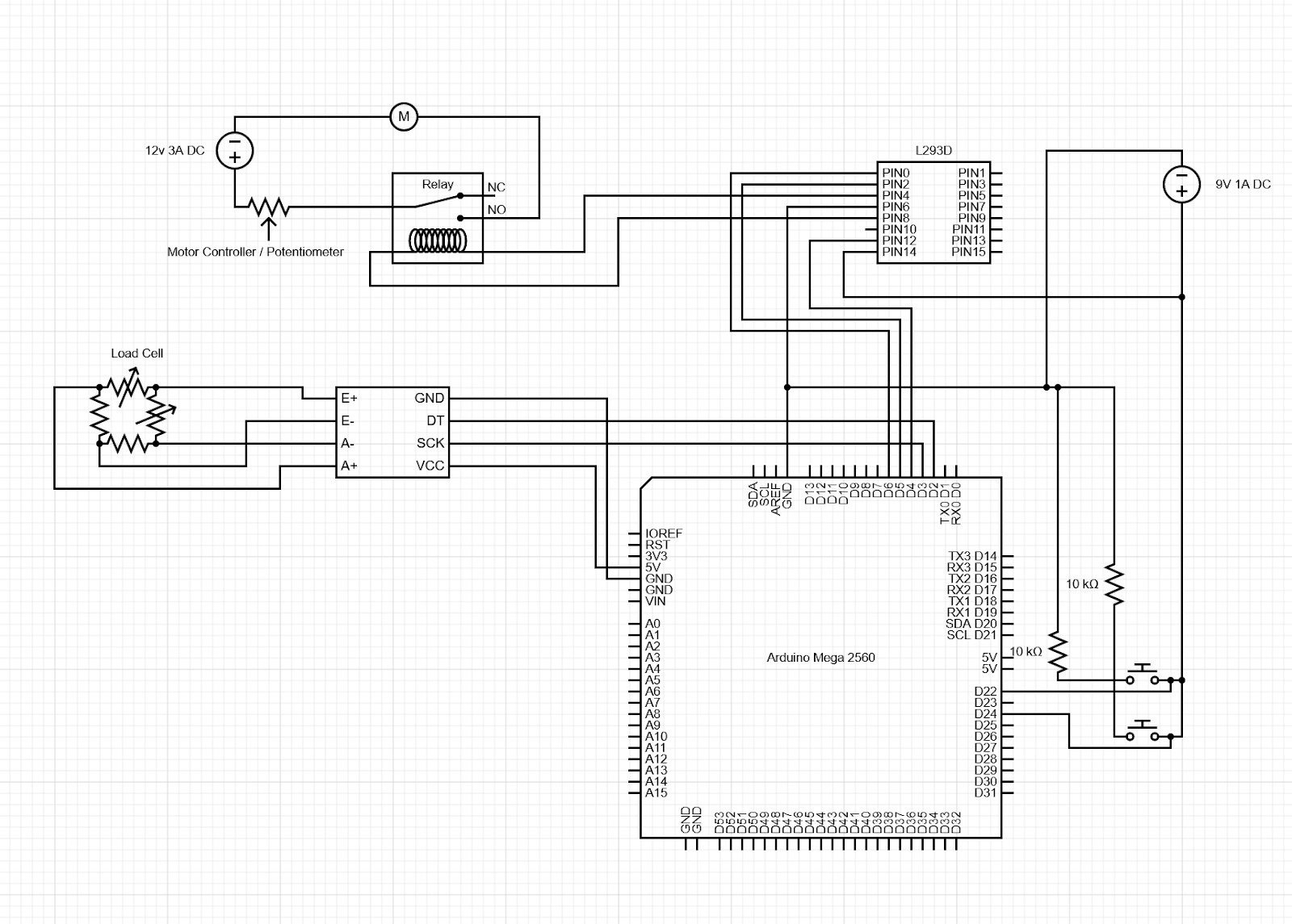
Circuit Diagram
References
“Auto-Destructive Art – Art Term | Tate”. 2021. Tate. https://www.tate.org.uk/art/art-terms/a/auto-destructive-art.
Elegoo. 12/12/2016. DC_Motor [Computer program]. Available at https://www.elegoo.com
Igoe, Tom. 9/04/2012. Smoothing [Computer program]. Available at https://www.arduino.cc/en/Tutorial/BuiltInExamples/Smoothing
Landy, Michael. 2001. Break Down. An Artangel Commission
Necula, Bogdan. 2021. HX711 (218) [Computer program]. Available at :https://github.com/bogde/HX711 (Accessed: 13/12/2021).HX711 Library, Bogdan Necula, https://github.com/bogde/HX711
Parker, Cornelia. 1991. Cold Dark Matter: An Exploded View. Installation. London: Tate Modern.
Tinguely, Jean. 1960. Homage To New York. Kinetic Sculpture. New York: Museum of Modern Art.

Leave a comment